Cost & ROI Series | Article 2
Series note: Article 1 explained why handheld laser welding cost should be measured per accepted meter. This article moves from cost to throughput and explains how to improve handheld laser welding efficiency without sacrificing first-pass quality.
Quick answer: Handheld laser welding efficiency is not simply travel speed. The useful measure is total cycle time per accepted part, including setup, fit-up, handling, welding, cleaning, inspection and rework. LNX Equipment recommends a 5-step throughput playbook: baseline one part family, measure the full cycle, identify the constraint, improve one bottleneck, then validate quality and re-measure.
A machine can weld at high speed and still create a bottleneck if the operator spends more time positioning, changing parameters, fixing fit-up or polishing the weld. Conversely, a modest travel-speed improvement can create meaningful capacity when it removes finishing or rework.
This guide gives small and mid-sized metal fabrication shops a practical way to measure handheld laser welding efficiency. It covers cycle time, throughput, arc-on ratio, the five welding modes, operator qualification and the real boundary of no-grind welding.
Why travel speed is not efficiency
Travel speed describes how fast the welding head moves while the laser is on. Efficiency describes how much accepted work leaves the cell in a given period.
That difference matters because total cycle time includes more than welding:
- Setup and parameter selection.
- Loading, unloading and fixture time.
- Fit-up and tacking.
- Laser-on time.
- Cleaning, grinding and polishing.
- Inspection and rework.
- Waiting for cooling, material or the next operation.
TWI notes that laser welding can achieve high speeds in thin materials, and its concentrated heat source can produce narrow welds with limited heat input. Those benefits are real, but they do not automatically turn into throughput. The shop still has to control fit-up, handling, mode selection and quality verification.
The practical rule is:
Efficiency = accepted output ÷ total production time
If two machines produce the same accepted parts, the one with the shorter total cycle time and lower rework is more efficient, even if its maximum travel speed is lower.
Figure 1: The 5-step handheld laser welding efficiency playbook. Step 1: Baseline one part family. Step 2: Measure the full cycle. Step 3: Identify the real constraint. Step 4: Improve one bottleneck at a time. Step 5: Validate quality and re-measure.
The 5-step efficiency playbook
Step 1: Baseline one part family
Do not measure the whole workshop at once. Select one representative part family with repeatable material, thickness and joint design.
Define the output before timing the process:
- What counts as an accepted part?
- Which defects require rework?
- Which operations belong to the welding cell?
- Which operations happen before or after the cell?
Without a clear acceptance rule, faster production can simply move defects downstream.
Step 2: Measure the full cycle
Time at least 20 parts, or enough parts to cover normal setup and variation. Record each time bucket separately.
| Time bucket |
What to measure |
Why it matters |
| Setup |
Fixture changes, parameter selection and first-piece checks |
Explains low-volume inefficiency |
| Load and position |
Handling, clamping, rotating and alignment |
Often the largest hidden time |
| Fit-up and tack |
Gap correction, cleaning and tack welds |
Drives rework risk |
| Laser-on |
Actual welding travel and interruptions |
The only time improved by travel speed |
| Finish |
Grinding, polishing, cleaning and heat-tint removal |
Determines no-grind potential |
| Inspection |
Visual checks, measurement and testing |
Protects quality but consumes capacity |
| Rework |
Repair, re-weld and re-inspection |
Reduces first-pass yield |
Use the same stopwatch rules for every operator and every process. Record the total and the individual time buckets.
Step 3: Identify the real constraint
Calculate arc-on ratio:
Arc-on ratio = laser-on time ÷ total cycle time
A low arc-on ratio means the process spends most of its time outside welding. Improving travel speed may have little effect.
Calculate cost and capacity using accepted output, not gross output:
Effective cycle time = total production time ÷ accepted units
First-pass yield = units accepted without rework ÷ total units started
Look for the largest recoverable time gap. It may be setup, handling, fit-up, cooling, finishing or rework. Improve the actual constraint first.
Step 4: Improve one bottleneck at a time
Change one variable, then measure again. Common improvements include:
- A fixture or stop that reduces alignment time.
- A standard parameter recipe by material and thickness.
- Pre-checking gap and surface condition before welding.
- Matching the wire feeder to the joint.
- Using the correct welding mode for the seam.
- Reducing unnecessary travel or repositioning.
- Separating tacking from final welding when it improves flow.
- Moving inspection earlier to catch defects before finishing.
Do not change power, mode, wire feed and fixture design at the same time. If the result improves, you will not know which change caused it.
Step 5: Validate quality and re-measure
A faster cycle is not an improvement if first-pass yield falls.
For each change, record:
- Total cycle time per accepted part.
- Arc-on ratio.
- First-pass yield.
- Rework minutes per accepted part.
- Consumable use per accepted meter.
- Operator variation.
Keep the change only if total cost per accepted part improves or capacity increases without creating new quality risk.
Figure 2: Seven time buckets that make up total cycle time per accepted part. The laser-on segment (highlighted) is the only portion improved by travel speed.
The metrics that matter
| Metric |
Formula |
What it tells you |
| Travel speed |
Weld length ÷ laser-on time |
Maximum process speed, not shop output |
| Arc-on ratio |
Laser-on time ÷ total cycle time |
How much time is spent welding |
| Effective cycle time |
Total time ÷ accepted units |
Real capacity per good part |
| First-pass yield |
Accepted without rework ÷ total started |
Quality and hidden capacity |
| Throughput |
Accepted units ÷ production time |
Output that can be shipped or used |
| Capacity released |
Baseline time − improved time |
Room for more work or shorter lead time |
Track these numbers for one month before making a large machine or fixture decision. A one-week sample can be distorted by a difficult batch, operator absence or material shortage.
What the speed numbers mean in practice
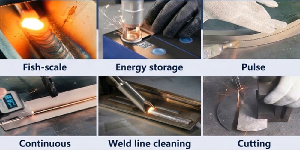
The LNX M4 air-cooled 1600W handheld fiber laser welder is listed with a welding speed of 10–30 mm/s, or approximately 0.6–1.8 m/min, depending on material, thickness, mode and joint. It also lists a rated welding depth of up to 4 mm and five modes: continuous, pulse, fish-scale, energy storage and interval.
Those are machine parameters. They are not a guarantee that every shop will complete every part at the maximum rate.
The same planning assumptions used in Article 1 can also show the throughput view:
- 10,000 accepted meters per year.
- 75% utilization.
- TIG at 0.3 m/min.
- Handheld laser at 1.2 m/min.
At those assumptions, TIG requires 740.7 paid process hours and the laser requires 185.2 hours. The difference is 555.5 process hours before considering extra finishing, rework or downtime.
The capacity released is meaningful, but it only becomes profit if the shop has more accepted work to fill the time. Otherwise, the benefit appears as shorter lead time, less overtime or better delivery reliability.
How to choose the five welding modes
Mode selection should follow the joint and acceptance criteria, not the mode that looks fastest in a demonstration.
| Mode |
Typical use |
What to verify |
| Continuous |
Long seams with stable gap and repeatable fit-up |
Heat input, distortion and travel stability |
| Pulse |
Thin or heat-sensitive parts where average heat must be controlled |
Penetration consistency and cycle time |
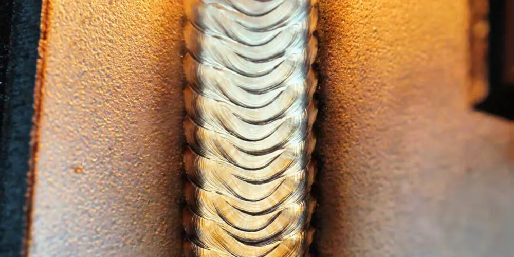
| Fish-scale |
Visible decorative seams and repeatable bead appearance |
Width, spacing, appearance and operator consistency |
| Energy storage |
Jobs requiring controlled energy delivery |
Actual power demand and parameter stability |
| Interval |
Stitch welds or precise spacing between weld segments |
Segment length, gap and structural requirement |
The M4 specification lists fish-scale welding within an 8 mm width and interval welding with precise spacing control. Those figures define a machine function, not a universal acceptance standard. Confirm the mode on the customer’s material, thickness and joint.
For wire-fed joints, remember that adding cold filler wire can reduce welding speed by roughly 10% to 20% at a given laser power because energy is needed to melt the wire. A wire feeder can improve fit-up tolerance or help control cracking, but it also changes the cycle.
Learning curve: build a qualified operator
The goal is not to make an operator “comfortable” with the machine. The goal is to produce acceptable parts repeatedly under production conditions.
Use a four-stage qualification path:
- Safety and setup: machine start-up, emergency stops, eyewear, barriers, gas and material handling.
- Coupon practice: one material, one thickness and one joint type per session.
- Production qualification: three consecutive accepted parts with no corrective rework.
- Speed and troubleshooting: mode changes, gap variation, cleaning and basic fault recognition.
Track first-pass yield, cycle time, rework minutes and parameter-setting errors. A faster operator who creates more rework is not more efficient.
No-grind welding: a result, not a promise
Handheld laser welding can reduce or eliminate post-weld grinding in suitable applications because the focused heat source produces narrow welds and limited distortion. TWI notes that low heat input can reduce thermal damage and distortion compared with many arc processes.
However, no-grind welding depends on the whole process:
- Clean material with consistent surface condition.
- Repeatable fit-up and gap.
- Correct gas coverage.
- Correct wire and feed rate.
- Suitable mode and travel speed.
- Stable fixture or positioning.
- An acceptance criterion for appearance and penetration.
| Condition |
Good sign |
Risk |
| Fit-up |
Consistent gap and alignment |
Gaps force filler and slower travel |
| Surface |
Clean, dry, oil-free |
Contamination causes porosity and rework |
| Mode |
Matched to seam and appearance |
Wrong mode creates excess heat or uneven bead |
| Gas |
Correct flow and coverage |
Oxidation, spatter and post-weld cleaning |
| Operator |
Qualified on the part family |
Results vary between shifts |
| Inspection |
Defined visual and penetration criteria |
A good-looking bead may still fail requirements |
Use a test coupon and a first-article inspection to decide whether grinding can be removed. Do not remove finishing from the process until the acceptance data supports it.
Typical shop scenarios
Stainless steel enclosures and cabinets
Long visible seams benefit from stable continuous or pulse settings, good fit-up and consistent handling. The efficiency gain often comes from less heat tint, distortion and polishing.
Aluminum panels and frames
Aluminum requires attention to surface preparation, gap control and heat input. Pulse or interval settings may help control appearance and distortion, but the operator must verify penetration and cycle time.
Kitchen equipment and architectural metalwork
Fish-scale mode can support a decorative appearance and repeatable spacing. The constraint is usually consistency, not maximum travel speed. Qualify the operator by appearance and acceptance criteria.
Thin and medium-gauge structural fabrication
Repeatable fixtures, standard parameter recipes and continuous or interval modes can improve flow. Keep the work within the verified thickness and power window.
Heavy sections
For thicker work, a water-cooled system such as the 3000W S7 with rated depth up to 7 mm may be more appropriate than an air-cooled unit. Joint preparation and fit-up become even more important.
Common efficiency mistakes
- Measuring travel speed but not total cycle time.
- Timing only the welder and ignoring handling and finishing.
- Using a polished demonstration coupon instead of the real part.
- Changing several parameters at once.
- Removing grinding before quality is verified.
- Training by observation without a qualification standard.
- Assuming a faster machine solves a fixture or fit-up problem.
- Measuring gross output instead of accepted output.
FAQ
How do you measure handheld laser welding efficiency?
Measure total cycle time per accepted part, not travel speed alone. Record setup, handling, fit-up, laser-on time, cleaning, inspection and rework. Then calculate arc-on ratio, first-pass yield and accepted units per production hour. The best improvement is the one that lowers total time per accepted part.
Is handheld laser welding faster than TIG welding?
It can be faster on suitable thin and medium-gauge work when fit-up, mode and handling are controlled. The practical advantage depends on total cycle time. A fast weld can still lose its benefit if setup, position, cleaning or rework takes longer than expected. Measure the same part family in both processes.
Can handheld laser welding eliminate grinding?
It can reduce or eliminate grinding in suitable applications with good fit-up, clean material, correct gas, correct wire and a verified process window. It is not automatic. Confirm appearance, penetration and customer acceptance on a test coupon before removing polishing or grinding from the work instruction.
Sources and methodology
This article separates external technical evidence, LNX product specifications and editable planning assumptions. The 10,000-meter example is a planning calculation, not a customer case or performance guarantee.
Next in the series
Request a 60-second test weld video





One thought on “Handheld Laser Welding Efficiency: The 5-Step Playbook 2026”
One practical note for buyers:
The numbers on a laser welder brochure are only the starting point.
A few things are easy to overlook when comparing machines:
• Higher laser power does not automatically mean higher productivity.
If your bottleneck is fit-up, handling, fixture changes or grinding, adding power may not solve the real constraint.
• Travel speed is not the same as production speed.
Always compare the complete cycle: setup → positioning → welding → finishing → inspection → rework.
• “No grinding” depends on the application.
Material condition, joint gap, wire, shielding gas, welding mode and operator consistency all affect the final result.
• Air-cooled vs. water-cooled should be matched to workload.
Intermittent workshop use and long continuous production have different cooling requirements.
• A real-part test is more useful than a maximum speed number.
Test the actual material, thickness, joint and acceptance criteria before making a machine decision.
If you’re evaluating handheld laser welding, send us:
Material + thickness + joint type + current welding process + welding hours/day
We can help you identify which factors are likely to affect your actual cycle time before choosing a configuration.